Maps, Axes and Checksums in WinOLS
When working with WinOLS, understanding maps, axes, and checksums is essential for professional ECU tuning. These three elements determine how engine data is interpreted, how modifications are applied across operating ranges, and whether a modified file remains valid for flashing. This article explains what maps, axes, and checksums are, how they relate to each other in WinOLS, and why they matter in professional tuning workflows.
In this article
What are maps in WinOLS?
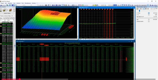
In WinOLS, a map is a structured block of data within an ECU file that controls a specific engine parameter.
Common examples include:
-
Torque limiters
-
Fuel quantity maps
-
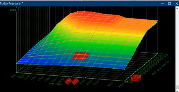
Boost pressure maps
-
Rail pressure maps
-
Smoke or lambda maps
Maps are typically displayed as:
-
2D maps (single value tables)
-
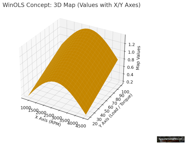
3D maps (tables with X- and Y-axes)
Each map defines how the ECU responds under specific operating conditions.
What are axes in WinOLS?
Axes define how and when map values are applied.
In most cases:
-
The X-axis represents engine speed (RPM)
-
The Y-axis represents load, torque, or air mass
-
The map values represent the ECU output (fuel, boost, pressure)
Without correctly defined axes:
-
Map values cannot be interpreted correctly
-
Changes may apply at the wrong RPM or load
-
Visual tuning decisions become unreliable
Axis validation is therefore just as critical as map identification.
How maps and axes work together
Maps and axes always operate as a unit:
-
Axes define when/where a value is used
-
The map defines what value is used
That’s why professional workflows verify:
-
Axis scaling (units and steps)
-
Axis ranges (min/max operating areas)
-
Map structure (dimensions, type, expected patterns)
What are checksums in WinOLS?
A checksum is a control value used by the ECU to verify the integrity of the data stored in memory.
When an ECU file is modified:
-
The original checksum often becomes invalid
-
The ECU may reject the file, fail to flash, or enter a safety mode
-
In some cases, the engine may not start or may operate in limp mode
WinOLS supports checksum correction depending on:
-
ECU type
-
Project configuration
-
Available checksum definitions or upgrades
Checksum handling is a mandatory step in any professional tuning workflow.
Why checksum correction is critical
Incorrect or missing checksum correction can result in:
-
Flashing errors
-
ECU startup problems
-
Fault codes or limp mode
-
Unpredictable engine behavior
For professional use, every modified file must have a valid checksum before flashing. If checksum handling is uncertain, the file should not be delivered or written to the ECU.
Checksum support, points and upgrades
Checksum support in WinOLS depends on the specific ECU type and the available checksum definitions.
Some ECUs:
-
Are fully supported out of the box
-
Require additional checksum definitions or upgrades
-
Have limited or no automatic checksum support
For a detailed overview of supported ECUs, checksum points, and available checksum upgrades in WinOLS, see:
WinOLS Checksum Points and Upgrades
(This page explains checksum-related options and requirements in detail.)
Common issues with maps, axes, and checksums
Incorrect map identification
Editing data that is not actively used by the ECU.
Missing or incorrect axes
Values applied at unintended RPM or load ranges.
Checksum not corrected
The ECU rejects the file or behaves unexpectedly after flashing.
These issues often occur when working without proper reference data or verification steps.
How this fits into a professional WinOLS workflow
A typical professional WinOLS workflow includes:
-
Analyzing the original ECU file
-
Identifying maps and validating axes
-
Applying calibrated changes
-
Correcting checksums
-
Validating the file before flashing
This structured approach ensures reliability, repeatability, and tuning quality.